PFRM30 vertical mill
使用手册
User manual

Jiangsu Pengfei Group Co., Ltd.
目 录
Catalog
第一部分 概述
Part One Summarize
第二部分 结构介绍及安装
Part Two Structure Introduction and Installation
一、结构及工作原理Structure and working principle
二、技术参数及性能Technical parameters and performance
三、设备安装Equipment installation
四、液压及润滑系统的酸洗安装Acid pickling installation of hydraulic and lubrication systems
第三部分 PFRM30立式磨调试及使用
Part Three Commissioning & usage of PFRM30 cement vertical roller mill
一、前言Foreword
二、磨机分部件试运行Sub-components test run of mill
三、立式磨整机空负荷试运行Non- load test run of vertical mill
四、立式磨带负荷试运行Load test run of vertical mill
五、人员培训Staff training
六、磨机操作Operation of mill
七、可能出现的问题及解决办法Possible problems and solutions
八、系统操作System Operation
第四部分 PFRM30立式磨维护及检修
Part Four Maintenance and overhaul of PFRM30 vertical mill
一、前言Foreword
二、磨机的维护保养及检修Maintenance and repair of mill
三、润滑表Lubrication table
第一部分 概述
Part One Summarize
PFRM30立式磨是江苏鹏飞集团股份有限公司荣誉产品,该型立式磨经多年生产实践考验,产品性能不断提高,逐步跨入国际同类产品先进行列,深得国内外广大用户青睐。
PFRM30 vertical mill is one of honor products of Jiangsu Pengfei Group Co., Ltd., through many years of production practice tests for this vertical mill, product performance continuously improved, gradually entered the international advanced level of similar products, won the majority of users at home and abroad.
PFRM30立式磨是一种技术性能优异的烘干兼粉磨设备,主要用于水泥的粉磨,也可广泛应用于建材、轻工、化工、火力发电等行业。该型立式磨具有粉磨效率高、电耗低、入料粒度大、产品细度易于调节、设备工艺流程简单、占地面积小、噪音低、扬尘小、使用维护简单、运行费用低、耐磨材料消耗少等优点。除此之外,该型立式磨还具有如下独特性能:
PFRM30 vertical mill is drying and grinding equipment with high technical performance, mainly used in cement grinding, it can also be widely used in building materials, light industry, chemical industry, power generation and other industries. The vertical mill is with high efficiency, low power consumption, large feeding size, product fineness is easy to adjust, equipment process is simple, small covering area, low noise, small fugitive dust, use and maintenance are simple, low costs for operating, less consumption for wear material and other advantages. In addition, the vertical mill also has the following unique features:
1.磨辊可用液压装置翻出机外,更换辊套衬板及磨机检修空间大,检修作业十分方便。
Move the roller out of the mill by the hydraulic unit, replace the roller sleeve lining and large maintenance space of mill, maintenance operations is very convenient.
2.磨辊辊套能翻面使用,延长了耐磨材料的使用寿命。
Grinding roller sleeve can be used upside down, extending the life of wear-resistant materials.
3.开机前无需在磨盘上布料,并且磨机可空载启动,免除开机难的烦恼。
Material layer is not required to form on the table before starting the mill, and mill can be start with non-load, eliminating worries of difficulty of starting.
4.采用磨辊限位装置,避免磨机工作时因断料而产生的剧烈震动。
Adopt limiting device of grinding roller, avoid the severe shock caused by breaking material during operation of mill.
5.采用新型磨辊密封装置,密封更加可靠,并且无需密封风机。
Adopt the sealing device of new grinding roller, the sealing is more reliable and sealing fan is not required.
6.磨辊轴承采用油浸式润滑,免去外循环润滑。
Grinding roller bearing adopts oil - immersed lubrication, eliminating the external circulation lubrication.
7.采用外循环系统,降低风环处的风速,减少立磨排风机功率,改善磨机的启动及停机条件,减少维护时的清料时间。
Adopt external circulation system, reduce wind speed at the wind ring, reduce exhaust fan power of vertical mill, improve the mill's start-up and shutdown conditions, and reduce time of clearing material during maintenance
第二部分 结构介绍及安装
Part two. Structure instruction and installation
一、 结构及工作原理
I. Structure and working principle
㈠.结构(见下图)
(i) Structure (see below picture)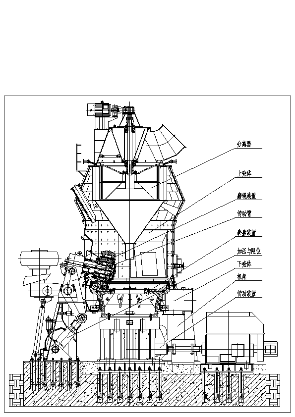
PFRM型立式磨作为一种新型节能粉磨设备,其工作原理是:
As the new type energy saving grinding equipment, the working principle of PFRM vertical mill is as follows.
电动机驱动减速机带动磨盘转动,需粉磨的物料由锁风喂料设备送入旋转的磨盘中心,在离心力作用下,物料向磨盘周边移动,进入粉磨辊道。在磨辊液压力的作用下,物料受到挤压、研磨和剪切作用而被粉碎。同时,热风从围绕磨盘的风环高速均匀向上喷出,粉磨后的物料被风环处的高速气流吹起,一方面把粒度较粗的物料吹回磨盘重新粉磨,另一方面对悬浮物料进行烘干,细粉则由热风带入分离器进行分级,合格的细粉随同气流出磨,由收尘设备收集下来即为产品,不合格的粗粉在分离器叶片作用下重新落至磨盘,与新喂入的物料一起重新粉磨,如此循环,完成粉磨作业全过程。
The motor drives reducer to drive the mill disk rotate. The material to be ground is fed to the rotating mill disk center by air lock feeder. The material moves to the mill disk circum and enters into grinding roller way under the effect of centrifugal force. Meanwhile, the hot air upward sprays uniformly at high speed from the air ring around mill disk. The ground material is blown by high speed air flow at air ring. The coarse material is blown to mill disk for regrinding. The suspended material is dried and the fine powder is fed to separator for grading by hot air. The qualified fine powder discharged from mill along with air flow and collected by dust collector is the product. The unqualified coarse powder re-falls to the mill disk under the effect of separator blade and is reground with new fed material. This process cycles until the grinding work is completed.
㈡.主要部件的结构形式及技术特点
(ii) Structural type and technical feature of main part
1.传动装置 Driving device
立式磨的传动装置由主电机、联轴器、减速机三部分组成,安装在磨机下部,既要带动磨盘传动,还要承受磨盘、物料、磨辊的重量以及加压装置施加的碾磨压力,是立式磨中最重要的部件之一。润滑系统采用独立的油站,并有油压、油温的自动保护系统,使全套装置工作安全可靠。该型式的减速机具有体积小、重量轻、减速比大、传动效率高等优点。关于主减速机的结构、工作原理等请详细查阅《MLX200立式磨减速齿轮箱使用维护说明书》。
The drive device of vertical mill contains main motor, coupling and reducer. It is installed in the bottom of the mill. It need to not only drive the mill disk to drive, but also bear the weight of mill disk, material and mill roller as well as grinding pressure brought by pressure device. It is one of the most important parts of vertical mill. Lubrication system adopts independent oil station with oil pressure and temperature automatic protection system to make the whole device work safely and reliably. This type of reducer has small volume, light weight, large reduction ratio and high driving efficiency. The structure and working principle etc. please refer to
2.碾磨装置 Grinding device
磨盘和磨辊是重要的研磨部件,它的形状设计必须使被粉磨的物料在磨盘上形成厚度均匀稳定的料床,因此合理的磨盘形状配以相适应的磨辊,对于稳定料层、提高粉磨效率、减少研磨消耗有着极为重要的作用。通过大量的调研和类比,我们采用盘形的磨盘形状和轮胎形辊套,辊套为对称结构,在磨损到一定程度后可翻面使用,延长其使用寿命。磨盘周边有可以调节料层厚度的挡料圈。
Mill disk and mill roller are important grinding parts. The shape design of the grinding device must make the material form material bed with uniform and stable thickness on the mill disk, so reasonable mill disk shape matched with suitable mill roller has very important effect in steadying material layer, improving grinding efficiency and reducing grinding consumption. Through a mass of researching and analogy, we use disk type mill disk and tyre type roller shell. Roller shell is symmetrical structure. It can be turn-over used after a certain wear to extend its service lift. The retention rings are located around the mill disk to adjust the thickness of material layer.
3.加压装置 Pressure device
采用液压自动或手动控制系统来施加及控制其对物料的作用力,可以根据物料易磨性的变化而自动地调整压力,因而使磨机经常保持在最经济条件下运行,这样,既可以减少无用功的消耗,又能使辊套、衬板的寿命得到延长。同时,由于蓄能器的缓冲作用,使液压缸施加压力具有较大的弹性,又可自动调节,当遇到大而坚硬的杂物时,磨辊可以跳起,从而避免粉磨部件及传动装置因承受过大荷载而损坏。
Pressure device adopts automatic or manual control system to impose and control its force to material. It can automatically adjust pressure according to the change of material grindability thus the mill always runs under the most economic conditions to reduce idle work consumption and extend the service life of roller shell and lining plate. Meanwhile, the buffer action of energy accumulator makes the hydraulic cylinder have large elasticity imposing pressure and adjust automatically. When meet large and hard sundries, the mill roller can jump to avoid damage caused by grinding part and driving device undertaking over load.
4.限位装置 Limit device
立式磨独特的限位装置可以使磨机轻载启动,磨辊和磨盘之间的间隙可调,这样既能保持稳定的料层厚度,提高粉磨效率,又能保证在断料等不正常情况下磨辊和磨盘不直接接触,避免磨机振动,对减速机起到保护作用。
The unique limit device of vertical mill can make the mill start under load. The gap between mill roller and mill disk can be adjusted. It can keep stable thickness of material layer, improve grinding efficiency, and ensure the mill roller and mill disk not contact directly under unnormal conditions such as material interrupt to avoid mill vibration thus protect reducer.
5.分离装置 Separating device
分离器设计为机械传动、转速可调的动态分离器,该分离器通过锥形转子高速回转,叶片与粗颗粒撞击,给物料以较大的圆周速度,产生较大的离心力,使其进行分离,细颗粒可通过分离器叶片之间间隙出磨,由收尘器进行收集。该分离器分级效率高,调节余地大。
The separator is a dynamic separator with mechanical drive and adjustable rotating speed. The cone rotor rotates in high speed and the blade impacts coarse particle to provide large circular velocity to the material and generate large centrifugal force to separate the material. The fine particle can be discharged from mill through the gap between separator blades and collected by dust collector. This separator has high grading efficiency and large adjusting scope.
6.磨辊装置 Grinding roller device
磨辊的装置是采用一对调心滚子轴承,设计时对轴承作等寿命计算,轴承密封腔延伸到机壳外,不与含尘气体接触,所以只用简单的填料密封就能保证磨辊轴承不进灰。磨辊设计为斜面安装,楔形环压紧,更换辊套十分方便。
Grinding roller device adopts a pair of self-aligning roller bearings. During design, make equal lift calculating for bearing. The seal chamber of bearing extends to the outside of mill shell. It doesn’t contact dust air so simple packing seal can ensure no dust enter into grinding roller bearing. Grinding roller is designed as slope installation and impacted by wedge shape ring to make the roller shell change easily.
7.磨机壳体及机架 Mill shell and frame
立式磨的壳体分为上壳体、下壳体和机架部分,每部分均采用螺栓连接,下壳体焊接在三个机架上。
Vertical mill’s shell divides into upper shell, lower shell and frame. Each part is connected by bolt. The lower shell is welded on three frames.
二、 技术参数及性能
II. Technical parameter and performance
㈠、 主要技术参数
(i) Main technical parameter
规格型号:Specification and type: PFRM30
磨盘中径:Mill disk intermediate diameter: φ2800
磨辊直径:Grinding roller diameter: φ1900mm
磨辊数量:Grinding roller no.: 3个
磨盘转速: Mill disk rotating speed: 28.5r/min
最大入料粒度:Max. feed size: ≤50mm
入磨物料水份:Material inlet moisture: ≤10%
产品细度:Product fineness 比表面积 Specific surface area ≥380m2/kg
产 量:Output: ≥65t/h
产品水份:Product moisture: ≤1.0%
入磨风温:Inlet air temperature: ≤350℃
出磨风温:Outlet air temperature: 80~90℃
出磨风量:Outlet air volume: 200000m3/h
磨机压降: Mill pressure drop: 5500~7500Pa
液压系统工作压力:Hydraulic system working pressure: 8~12Mpa
磨机外形尺寸:Mill overall dimension: 长:Length: 12000mm
宽:Width: 9380mm
高:Height: 13433mm
磨机总重量:Mill total weight: 328000kg
㈡、 主电机
(ii) Main motor
型号:Type: YRKK710-6
功率:Power: 1800KW
频率:Frequency: 60Hz
转速:Rotating speed: 1192r/min
电压:Voltage: 10KV
防护等级:Protection grade: IP54
㈢、 主减速机
(iii) Main reducer
生产厂家:南京高精齿轮股份有限公司
Manufacturer: NGC
型 号:Type: MLX200
数 量:Qty.: 1台set
传动功率:Driving power: 1800kW
速 比:Speed ratio: 41.8
额定轴向推力:Rated axial thrust: 5100kN
最大轴向推力:Max. axial thrust: 16600kN
服务系数: Service factor ≥2.5AGMA
旋转方向:从上往下看,推力盘为顺时针方向旋转
Rotating direction: look at it from above, thrust disk rotates clockwise
润滑油进、出口油管侧向:人站在输入轴端面向减速机,进油口2个、出油口1个
Lubricating oil inlet and outlet oil tube side direction: people stands at input shaft end and faces to reducer, two oil inlets, one oil outlet
㈣、高低压稀油站及辅助油箱
(iv) High and low thin oil station and auxiliary oil tank
型 号:Type: XGD-C160-500
生产厂家:四川川润股份液压润滑有限公司
Manufacturer: Sichuan Chuanrun Group Hydraulic Lubrication Co., Ltd.
润滑油量:Lubrication oil volume: 500L/min(低压部分low pressure part);160L/min(高压部分high pressure part)
润滑油压:Lubrication oil pressure高压:High pressure: 32MPa; 低压:Low pressure: 0.2~0.4MPa
润滑油品:N320中负荷工业齿轮油
Lubrication oil quality: N320 medium load industrial gear oil
环境温度:Ambient temperature: -20℃ ~ +40℃
冷却水量:Cooling water consumption: 30m3/h
冷却水温:Cooling water temperature ≤28℃,
工作班制:100%工作负荷,每天连续工作24小时
Work shift: 100% working load, continuous working 24 hours everyday
㈤、分离器
(v) Separator
电机型号:Motor type: YVF355M-6
电机功率:Motor power: 160KW
频率:Frequency: 60Hz
电机转速:Motor rotating speed: 0~1200r/min
减速机型号:Reducer type: B2SV07
旋转方向: 从上往下看,输出轴为顺时针方向旋转
Rotating direction: look at it from above, output shaft rotates clockwise
减速机比:Reducer speed ratio: 5.6
润滑油: 320#工业齿轮油
Lubrication oil: 320# industrial gear oil
㈥、液压系统
(vi) Hydraulic system
型号:Type:
液压泵电机功率:Hydraulic pump motor power: 18.5KW
工作压力:Working pressure: ≤12MPa
最大压力:Max. pressure: 20MPa
流量:Flow rate: 58L/min
液压油: N46抗磨液压油
Hydraulic oil: N46 antiwear hydraulic oil
油箱容积:Oil tank volume: L
三.设备安装
III. Equipment installation
㈠、准备工作
(i) Preparatory work
1. 水平测量仪;Horizontal measuring gauge
2. 框式水平仪(精度0.02mm/M);Frame level meter (accuracy 0.02mm/M)
3. 起重设备,各种常用工具;Hoisting equipment, kinds of general tools
4. 塞尺Filler gauge(0.05~1.00mm);
5. 垫铁Sizing block(规格specification 300×200×25)、楔铁若干some wedges(用户自备user provides);
6. 基础划线:Foundation lineation
首先将设备基础清理打扫干净,尤其是地脚螺栓孔内不得有积水、木块、碎石等杂物。为了二次灌浆结合紧密,基础表面必须凿毛,基础周围应填平、夯实。
Firstly, clean the equipment foundation. There should be no water, wood block, gravel inside the foundation bolt hole. For the tight combination of secondary grouting, the foundation surface should be roughened and the circum should be filled and leveled up as well as tamped.
其次对照土建图,安装图和设备实际尺寸,对设备基础进行校核和验收,内容包括检查土建单位提供的中心线、标高点是否正确,结合设备和工艺图检查基础的外形尺寸、基础标高尺寸、基础地脚螺栓孔的几何尺寸及相互位置尺寸等。
Secondly, check and accept the equipment foundation according to the construction layout drawing, installation drawing and equipment actual dimension. The content includes checking if the centerline and elevation point provided by the construction company is correct, and checking foundation overall dimension, foundation elevation dimension, foundation bolt hole’s physical dimension and mutual position dimension according to equipment and process drawing.
按设计图纸坐标位置,用钢盘尺测量出设备基础中心线,并将纵横中心线固定在中心标板上或用墨线划在基础上,并在安装过程中注意保留。
According to the coordinate position in design drawing, measure equipment foundation centerline by steel tape and fix the vertically and horizontally centerline on center board or mark it out on the foundation by chalk line. Pay attention to keep it during installation.
㈡.安装工作
(ii) Installation work
1.按照PFRM30立式磨基础图要求,检查地脚孔的位置及予留孔尺寸是否和设备相吻合。
According to the requirement of PFRM320 vertical mill foundation drawing, check if the foundation hole position and reserved hole dimension can fit the equipment.
2.检查设备地脚孔的尺寸,协调各地脚孔的偏差确定相对中心。
Check equipment foundation hole dimension and coordinate each foundation hole’s deviation to confirm relative center.
3.传动装置的安装:Driving device installation
根据土建施工图找出±0.00平面,使磨机安装标高符合工艺施工图要求。
Find out ±0.00 plane according to construction working drawing to make mill installation elevation conform to the requirement of process working drawing.
首先安装减速机底座,穿好地脚螺栓孔,螺栓要处于自然状态,分别在各地脚孔的中心。
Firstly install reducer base and perforate foundation bolt hole. The bolt should be in the raw and in the center of each foundation hole.
主减速机及其底座的安装是整个磨机安装的核心,其他零部件的安装必须以主减速机的中心为基准,因此主减速机应定位准确,其中心与基础中心应重合,偏差不大于±5.0mm。
The installation of main reducer and its base is the core of the whole installation. The installation of other parts must take main reducer center as datum. Therefore, the location of main reducer should be accurate. Main reducer center should coincide with foundation center and the deviation is not more than ±5.0mm.
在进行主减速机底座的安装时,应在每个地脚螺栓旁放置一组垫铁,每组垫铁不应超过四块,其中一对为斜垫铁,斜垫铁露出底座外的长度~30mm,垫铁与垫铁之间,垫铁与底座之间应紧密贴合。地脚螺栓在孔内应自然下垂,不应碰孔底和孔壁,螺栓应露出螺母2—3扣螺纹。
During installation of main reducer base, a group of sizing blocks no more than 4 pieces should be put at the side of each foundation bolt. Among them, there is a pair of wedge liners. The length of wedge liner came out of base is about 30mm. Each sizing block should closely fit sizing block and base. The foundation bolt should naturally fall in the hole without touching hole bottom and wall. The bolt should come out of nut 2-3 threads.
地脚孔灌浆前应将孔壁用水淋湿,并再次确认底座位置、标高是否准确。灌浆时应将混凝土捣实,并防止地脚螺栓歪斜。灌浆后须每天加水养护,直到混凝土强度达到规定强度的75%。
Before foundation bolt grouting, wet the hole wall with water and recheck if the base position and elevation are correct. During grouting, tamp the concrete to avoid foundation bolt deflect. After grouting, make water maintenance everyday till the concrete strength reaches to specified 75%.
拧紧地脚螺栓时,应使每个地脚螺栓均匀受力。调整底座水平时,必须使用垫铁来调整,不得用拧紧或放松地脚螺栓的办法来调整,其水平度应达到0.1mm/m。完成后,垫铁与垫铁之间,垫铁与底座之间应点焊固定。
When screw up foundation bolt, make every foundation bolt get uniform force. Must use sizing block to adjust base level must not screw up or relax foundation bolt to adjust. The levelness should reach to 0.1mm/m. After completing, spot weld between sizing block and sizing block as well as sizing block and base to fix them.
主减速机与底座联接时应预先将定位销装好,再装联接螺栓,拧紧螺栓时,应使每个螺栓受力均匀。
When connect main reducer and base, pre-install locating pin and then install connecting bolt. When screw up bolt, make each bolt get uniform force.
安装主电机时,应先将主电机与底板用螺栓联接成一体,并在主电机与底板间加垫~2.0mm。每个底板地脚螺栓旁放置一组垫铁,地脚螺栓在孔内应自然下垂,并使主电机与主减速机中心对中找正,定位后在地脚孔内灌浆捣实,经养护待混凝土强度达到规定强度75%时,拧紧地脚螺栓,通过垫铁调整水平,并使主联轴器达到规定的要求(详见《MLX200立式磨减速齿轮箱使用说明书》)。安装完毕后,垫铁与垫铁之间,垫铁与底板之间应点焊固定。
When install main motor, firstly connect main motor and base plate by bolt and add pad about 2.0mm between main motor and base plate. Put a group of sizing blocks at the side of each foundation bolt. The foundation bolt should naturally fall in the hole to make main motor center align to main reducer center. After locating, grout inside the foundation hole and tamp it. After the concrete strength reaches to specified 75% through water maintenance, screw up foundation bolt and adjust level by sizing block to make main coupling reach specified requirement (see
安装主电机和减速机时,要求联轴器的径向跳动不大于0.1mm,端面跳动不大于0.08mm,两联轴器间的距离8~10mm。(具体见减速机安装说明书)
When install main motor and reducer, the radial run-out of coupling should be no more than 0.1mm, the end face run out should be no more than 0.08mm and the distance between two couplings is 8-10mm (details see reducer installation instruction).
4.下壳体、磨盘安装:Lower shell and mill disk installation
(1)、PFRM30立式磨的机架、下壳体部分由于起吊和运输问题,必须在现场焊接,现场安装时要按照设备制造厂对各部件的标记进行安装。
Due to hoisting and transporting of PFRM30 vertical mill frame and lower shell, they should be welded on site and installed according to MARK of each part made by manufacturer.
安装下壳体时应以减速机出轴中心线为基准,两者中心线间的误差不得超过±2.0mm。
Lower shell installation should take reducer output shaft centerline as datum. The deviation between two centerlines should be no more than ±2.0mm.
将机架部分按上面标记吊装到相应基础上,按图纸要求确定三个机架的正确位置,用连接杆将三个机架初步连接在一起, 地脚螺栓挂好。
Hoist the frame according to MARK to the corresponding foundation. Confirm the correct locations of three frames. Preliminarily connect three frames together by connecting rod and hang foundation bolts.
(2)、将下壳体吊装到机架上 Hoist lower shell to the frame
利用十字交叉天线来确定筒体中心和减速机出轴中心线之间的同心度,将机架和下壳体焊接在一起,焊缝均为连续角焊缝,焊缝高度为15~20mm,坡口型式及尺寸要符合GB985-88中的要求。
Use cross antenna to confirm the concentricity between shell center and reducer output shaft centerline. Weld frame and lower shell together. The welding line is continuous fillet weld. The welding line height is 15-20mm. The groove type and dimension should conform to the requirement of GB985-88.
(3)、磨盘轻轻吊装在减速机上,找正并装上定位销,均匀用力拧紧联接螺栓,通过调整下壳体的位置,使磨盘与风环间的径向间隙基本一致(误差不得超过±2.0mm,沿磨盘周边对称选八处进行检查),同时检查下壳体上法兰与磨盘上端面间的轴向距离是否满足安装要求,PFRM2800立式磨下壳体上法兰与磨盘上端面间的轴向距离设计为45mm,可通过调整垫铁进行调整。
The mill disk is lightly hoisted on the reducer. Align and install locating pin, and uniformly screw up connecting bolt. Make the radial clearance between mill disk and air ring basic uniform by adjusting the position of lower shell (the deviation should be no more than ±2.0mm, choose 8 symmetric points along the mill disk circum to check). Meanwhile, check if the axial distance between lower shell upper flange and mill disk upper end face can meet installation requirements. The axial distance between PRM2800 vertical mill lower shell upper flange and mill disk upper end face is designed as 45mm. It can be adjusted by adjusting sizing block.
(4)、对机架的地脚螺栓孔进行一次灌浆。
Make one time grouting for frame’s foundation bolt.
(5)、七天后精校下壳体水平(既6个轴承座的水平)。6个轴承座的高度误差不大于2mm。
Accurately adjust lower shell level (that is the level of 6 bearing seats) after 7 days. The height deviation of 6 bearing seats should be no more than 2mm.
最后拧紧地脚螺栓。Screw up foundation bolt at last.
5.上壳体、磨辊及传动臂的安装 Installation of upper shell, grinding roller and transmission arm
按设备图纸要求将上壳体吊装到下壳体上,找正后均匀用力紧固联接螺栓。将事先组装好的磨辊和传动臂吊装到下壳体机架的轴承座上,使磨辊轻轻置于磨盘上,滑动轴承上涂润滑脂,拧紧轴承座的联接螺栓,再安装磨辊的密封门,安装时应注意密封的严密性。
Hoist upper shell on lower shell according to equipment drawing requirement. Align and fasten connecting bolt with uniform force. Hoist the assembled grinding roller and transmission arm on the bearing seat of lower shell frame. Lightly put the grinding roller on the mill disk. Coat lubrication grease on sliding bearing and screw up connecting bolt of bearing seat and then install the sealing door of grinding roller. Pay attention to the leakproofness of sealing during installation.
6.限位装置及分离器的安装 Installation of limit device and separator
预先组装好限位装置,按设备基础图尺寸要求将其就位,并拧出限位螺栓使其与限位头相接触,找正后对地脚螺栓灌浆将其固定,待砂浆凝固后,拧紧地脚螺栓。然后再拧出限位螺栓,使磨辊与磨盘之间的距离为5~10mm。接着开始安装分离器,将预先组装好的分离器吊装到上壳体上并找正水平,均匀用力拧紧联接螺栓,注意法兰接合面要求严格密封。
Assemble limit device in advance. Take it to the place according to the dimensional requirement of equipment foundation drawing and screw out limit bolt to make it contact with limit head. Align and grout foundation bolt to fix it. After the mortar solidified, screw up foundation bolt. Then screw out limit bolt again to make the distance between grinding roller and mill disk in 5-10mm. Next install separator. Hoist assembled separator on upper shell and align. Screw up connecting bolt with uniform force and pay attention to strictly seal the flange mating face.
7.加压装置的安装 Installation of pressure device
将组装好的加压装置按图纸要求就位,与磨机主体相联后找正,按图纸要求检查工作缸,检修缸的两中心孔距,将地脚螺栓灌浆固定,砂浆凝固后拧紧螺栓。
Take the assembled pressure device to the place according to drawing requirement. Align after connecting it with mill body. Check the center hole distance between working cylinder and inspection cylinder according to drawing requirement. Grout foundation bolt to fix it and screw up bolt after the mortar solidified.
8.液压系统及润滑系统的安装 Installation of hydraulic system and lubrication system
根据设备安装现场的实际情况,备齐液压系统及润滑系统所需的各种规格油管,用压缩空气吹扫管孔并严格清洗干净,分别按要求进行组合和安装。
As per the actual condition on site of equipment installation, prepare all kinds of oil pipe for hydraulic system and lubrication system. Blow the pipe hole by compressed air and clean up strictly. Respectively assemble and install as requirements.
制作管路时,焊缝应连续严密,管路制作完毕后,每节管路应先压缩空气反复吹扫,再用稀盐酸清洗,最后用清洗油仔细清洗。安装主减速机至润滑站的回油管路时,须有≧3/100的斜度,以保证回油顺畅。润滑管路上的联接法兰、液压管路上的管接头应密封严密,不得漏油。液压管路中与主油缸或检修油缸联结部分应用高压软管,蓄能器可用支架固定在油缸附近的磨机下机架上,液压管路应每隔一段距离(大约2M)用管夹固定。
When make pipelines, the welding line should be continuous and tight. After finish them, each section of pipelines should be blown repeatedly by compressed air and cleaned by diluted hydrochloric acid and at last cleaned carefully by cleaning oil. When install the oil return pipeline from main reducer to lubrication station, the pipeline should have the slope ≧3/100 to make the oil return smoothly. The connecting flange on lubrication pipeline and pipe connection on hydraulic pipeline should be sealed tightly without oil leakage. Use high pressure hose for the connecting part of hydraulic pipeline and main oil cylinder or inspection oil cylinder. The energy accumulator can be fixed on the mill lower frame near oil cylinder by support. Hydraulic pipeline should be fixed by pipe clamp at a distance of about 2m.
最后对设备基础进行整体二次浇灌(下壳体的两机架内部应予埋排水管)。
At last, make secondary grouting to the whole equipment foundation (pre-embed drainage pipe inside two frames of lower shell).
四.液压及润滑系统的酸洗
IV. Acid cleaning of hydraulic and lubrication system
液压管道安装分两步进行,第一步为预安装(配管),第二步为正式安装。预安装是为正式安装作准备,是确保安装质量的必要步骤。
The first step of hydraulic pipeline installation is pre-installation (piping) and the second step is formal installation. Pre-installation is to make preparation of formal installation. It is a necessary step to ensure installation quality.
按液压原理图及管道安装示意图现场制作。
Fabricate on site according to hydraulic principle drawing and pipeline installation drawing.
㈠、预安装(配管)
(i). Pre-installation (piping)
1.PFRM型系列立式磨的液压管路系统一般采用无缝钢管、高压橡胶软管等
The hydraulic pipeline system of PFRM vertical mill usually uses seamless steel tube and high pressure hose etc.
2.根据工艺设计和现场的具体情况,首先确定液压站的位置。
As per process design and actual condition on site, firstly confirm the location of hydraulic station.
3. 配管,管接头和主管焊接要平直,焊缝要均匀,不得有气孔、裂纹等影响管路压力泄漏的缺陷存在,条件允许的厂家应进行压力试验。
The welding of piping, pipe connection and main pipe should be straight. The welding line should be uniform without defect such as air hole or crack which may cause pipeline pressure leakage. The manufacturer should take pressure test if he has such ability.
4.各管作记号卸下,准备进行清洗。
Mark each pipe and discharge for cleaning.
5.酸洗 Acid cleaning
一般按下列程序进行 Common process
脱脂→水冲洗→酸洗→中和→水冲洗→干燥空气吹干→涂液压油
Degrease-water washing-acid cleaning-neutralize-water washing-dry by dry air-coat hydraulic oi
具体步骤如下:Detailed steps are as follows.
(1)、用榔头对油管逐点敲打,特别是对焊接处,以达到清除管道内的氧化皮和焊渣、毛刺。
Beat the oil pipe point to point especially to the welded part by hammer to clean up oxide skin inside pipeline as well as welding slag and burr.
(2)、用浓度8~10%的氢氧化钠溶液灌入油管内,浸泡3~4小时,然后用清水冲洗。
Pour sodium hydroxide solution with 8-10% concentration into oil pipe for 3-4 hours and then use water to wash.
(3)、用浓度15%的盐酸溶液或磷酸溶液灌入油管内,浸泡6~8小时,然后倒出酸液,再向油管内灌入浓度10%苏打溶液浸泡1小时后,用清水冲洗,压缩空气吹干,机油浸泡1小时。
Pour hydrochloric acid or phosphoric acid solution with 15% concentration into oil pipe for 6-8 hours. Then pour out acid solution and pour soda solution with 10% concentration into oil pipe for 1 hour. After that, use water to wash and dry by compressed air and then pour into machine oil for 1 hour.
(4)、干燥空气吹干。
Dry by dry air.
㈡.正式安装
(ii) Formal installation
1. 酸洗后的管道按原作记号安装回原处,并用相应的管卡固定。
Install the acid cleaned pipeline to the original place as per marks and fix it by corresponding pipe clamp.
2.连接高压软管、蓄能器。
Connect high pressure hose and energy accumulator.