Chapter 6 Equipment Installation Requirements
辊压机在出厂时主要是分为四大部分运输的。一:主机部份,包括主机架、进料装置、液压装置、润滑系统; 二:两套轴系;三:行星减速器; 四:主电机; 另外还有附属配套设备。因此初次在现场安装工作量较小。主要是安装传动系统各部件。为了使用户在设备检测和保养时,能正常安装各个零、部件,保证设备正常使用,提出如下要求,请用户务必遵行。
The roller press is mainly divided into four parts for transportation when it leaves the factory. One: The main machine part, including the main frame, feeding device, hydraulic device, and lubrication system; Two: Two sets of shafting system; Three: Planetary reducer; Four: Main motor; In addition, there are auxiliary equipment. Therefore, the initial installation workload on site is relatively small. Mainly install the components of the driving system. In order to enable the user to install various parts and components normally during equipment inspection and maintenance, and to ensure the normal use of the equipment, the following requirements are proposed, which the user must comply with.
一.各部件、系统总安装顺序
1. The overall installation sequence of components and systems
1.安装主机部分;
1. Install the main machine part;
⑴设备进厂初次安装;
⑴The first installation of equipment into the factory;
⑵安装主电动机;
⑵Install the main motor;
⑶安装行星减速器;
⑶ Install planetary reducer;
⑷校正主电机位置并安装万向节传动轴;
⑷ Correct the position of the main motor and install the universal joint drive shaft;
⑸安装扭矩支承装置。
⑸ Install torque support device.
2.各装系统、部件安顺序框图
2. The sequence diagram of the installation system and components
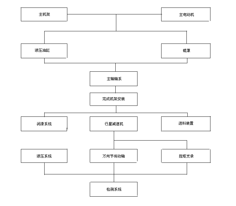
主机架main frame 主电动机main motor
液压油缸Hydraulic cylinder 辊罩roller cover
主轴轴系main shaft system
完成机架安装complete the installation of frame
润滑系统Lubrication system 行星减速机Planetary reducer 进料装置feeding device
液压系统hydraulic system 万向节传动轴Universal joint drive shaft 扭矩支承Torque support
检测系统Detection system
二.主机架安装
2. Main frame installation
1. 主机架一般是做为一个整体出厂,其安装顺序如下:
1. The main frame is generally shipped as a whole, and the installation sequence is as follows:
⑴以两立柱的承载销和定位销为基本定位,用高强度螺栓组将上、下横梁与左右立柱联接成一整体。在此应注意承载销与销孔是配作的,安装时应分清配对的标记。
⑴ With the bearing pins and positioning pins of the two columns as basic positioning, the upper and lower beams and the left and right columns are connected into a whole with the high-strength bolt group. It should be noted that the bearing pins and pin holes are matched, and the matching marks should be distinguished during installation.
⑵将四条导轨安装于机架的内腔上,四条导轨分两种规格,宽度有所不同,两条较宽的应安装于靠近传动侧,即安装于靠近主电机一侧。
(2) Install the four guide rails on the inner cavity of the rack. The four guide rails are divided into two specifications with different widths. The two wider ones should be installed near the drive side, that is, the side near the main motor.
2.将主机架吊装至预定的安装位置。注意只能使用下横梁的吊装孔避免机架联接螺栓受力。
2. Hoist the main frame to the predetermined installation position. Note that only the lifting holes of the lower beam can be used to avoid stress on the frame connecting bolts.
3.按照工艺设计图纸校正主机架的水平位置及标高。必需注意主机架与两主电机的相对位置。
3. Correct the horizontal position and elevation of the main frame according to the process design drawings. It is necessary to pay attention to the relative position of the main frame and the two main motors.
4.用水平仪校正主机架的水平,使主机架平面度公差小于2mm/m。
4. Use the spirit level to correct the level of the main frame so that the flatness tolerance of the main frame is less than 2mm/m.
5.在机架完全安装完毕后,应用力矩搬手拧紧高强度螺栓组,拧紧力矩为750N.m。
5. After the rack is completely installed, the high-strength bolt group should be tightened with torque hand, and the tightening torque is 750N.m.
6.在机架联接螺栓拧紧,并确认立柱与横梁接合面无缝隙后,方可拧紧地脚螺栓。
6. The anchor bolts can be tightened only after the frame connecting bolts are tightened and the joint surface of the column and the beam is confirmed to be seamless.
三.主轴轴系安装
3. Main shaft system installation
轴系在出厂时是做为一个部件装配好的,使用单位在将其安装到位前,必须做一次全面的检查,以保证以后的装配质量,其装配顺序如下:
The shaft system is assembled as a component when it leaves the factory. Before installing it in place, the user must do the comprehensive inspection to ensure the quality of subsequent assembly. The assembly sequence is as follows:
1.松开并吊装下主机架的横梁。
1. Loosen and hoist the beam of the lower main frame.
2.因每套轴系重达26t,为防止起吊时整个轴系发生弯曲变形,我们建议起吊时用角钢或槽钢焊制一个矩形框架撑住四个起吊点。
2. Since each shaft system weighs 26t, in order to prevent bending and deformation of the entire shaft system when lifting, we recommend using angle steel or channel steel to weld the rectangular frame to support the four lifting points when lifting.
3.起吊固定辊轴系,将其固装于主机架的左立柱侧。
3. Lift the fixed roller shaft system and fix it on the left column side of the main frame.
4.在吊装活动辊轴系时,先在其轴承座的上、下槽内涂以适量的润滑脂,并以靠近传动侧的导轨为定位基准,将轴系装于主机架内腔。
4. When hoisting the movable roller shaft system, apply proper amount of grease to the upper and lower grooves of the bearing seat first, and install the shaft system in the inner cavity of the main frame with the guide rail near the driving side as the positioning reference.
5.在保证导轨不与活动辊轴承座发生干涉的前提下,尽量调整磨辊的位置,使两磨辊的工作段端面保持在同一垂直面内,这样一方面可尽量增加工作段宽度,另一方面可使进料装置中的侧挡板尽量靠近磨辊端面,减少端面漏料,降低边缘效应.
5.Under the premise of ensuring that the guide rail does not interfere with the movable roller bearing seat, adjust the position of the grinding roller as much as possible to keep the end faces of the working section of the two grinding rollers in the same vertical plane, so that on the one hand, the width of the working section can be increased as much as possible, and on the other hand, the side baffle in the feeding device can be made as close as possible to the end surface of the grinding roller to reduce the material leakage of the end surface and reduce the edge effect.
6.在两磨辊安装到位后,安装位于两磨辊之间的中间架,在安装时必须保证两点:⑴中间架与固定辊之间不能留有间隙,因中间架的作用就是将无物料挤压时作用于活动辊上的液压力通过固定辊传递到主机架,从而在主机架上平衡的,若二者之间留有间隙,则液压直接作用在中间架上,有可能剪断中间架与上、下横梁的联接螺栓;⑵为了防止无物料时,活动辊碰撞到固定辊,必须保证一定的原始缝,因此在中间架与活动辊之间必须加设垫板,以确保留有15mm的原始辊缝。
6.After the two grinding rollers are installed in place, install the intermediate frame between the two grinding rollers. Two points must be ensured during installation: ⑴There must be no gap between the intermediate frame and the fixed roller, because the role of the intermediate frame is to transfer the hydraulic pressure acting on the movable roller when there is no material squeezing to the main frame through the fixed roller, so as to balance on the main frame. If there is gap between the two, the hydraulic pressure directly acts on the middle frame, and it is possible to cut the connecting bolts between the middle frame and the upper and lower beams; ⑵In order to prevent the movable roller from colliding with the fixed roller when there is no material, a certain original gap must be ensured. Therefore, the base plate must be added between the intermediate frame and the movable roller to ensure that the original roller gap of 15mm is left.
安装轴系水冷系统时,应确保旋转接头与主轴中心孔的同心度,以防止旋转接头跟转。
When installing the shafting water-cooling system, ensure the concentricity of the rotary joint and the center hole of the main shaft to prevent the rotary joint from rotating.
四.主电机及控制装置安装
4. Installation of main motor and control device
⑴以固定辊中心线为基准,校正固定辊驱动电机的水平及垂直位置,必须保证:
⑴Taking the centerline of the fixed roller as the reference, correcting the horizontal and vertical position of the fixed roller driving motor, you must ensure:
Ⅰ 电机轴线与磨辊轴线同轴度为0.2mm。
Ⅰ The coaxiality between the motor axis and the grinding roller axis is 0.2mm.
Ⅱ 两轴线夹角小于2°。
Ⅱ The angle between the two axes is less than 2°.
⑵主电机的地脚螺栓需在万向传动轴安装完毕,并再次校对与磨辊轴线位置后,方可拧紧。
⑵The anchor bolts of the main motor can be tightened only after the universal joint shaft is installed and the position of the grinding roller axis is checked again.
⑶在接冷却风机电机电源时,应注意风叶的转向,以避免反接。
⑶ When connecting the cooling fan motor power, pay attention to the direction of the fan blade to avoid reverse connection.
五.行星减速器及缩套联轴器的安装
5. Installation of planetary reducer and shrink sleeve coupling
1.缩套联轴器的安装
1. Installation of shrink sleeve coupling
⑴用汽油清洗缩联轴器,在锥面、螺孔及螺杆均匀地涂一层10#或20#机械油,注意不得采用含有二硫化钼的润滑油和脂。
⑴ Clean the shrink coupling with gasoline, and coated a layer of 10# or 20# mechanical oil evenly on the cone surface, screw hole and screw rod. Be careful not to use lubricating oil and grease containing molybdenum disulfide.
⑵将缩套联轴器套于已清洗干净的行星减速器中空输出轴上,并推至输出轴轴颈的圆弧边缘位置。
⑵Sleeve the shrink sleeve coupling on the hollow output shaft of the planetary reducer that has been cleaned, and push it to the arc edge of the output shaft journal.
2. 行星减速器的安装
2. Installation of planetary reducer
⑴在安装前先用手盘动其输入轴,看其内部运转是否灵活;
⑴ Rotate the input shaft by hand before installation to see if its internal operation is flexible;
⑵用汽油将行星减速器中空输出轴和磨辊主轴轴颈清洗干净;
⑵ Use gasoline to clean the hollow output shaft of the planetary reducer and the main shaft journal of the grinding roller;
⑶将缩套联轴器套于减速器中空轴上;
(3) Put the shrink sleeve coupling on the hollow shaft of the reducer;
⑷起吊减速器使其轴线与磨辊主轴轴线尽可能保持一致;
⑷ Lift the reducer so that its axis is as consistent as possible with the axis of the grinding roller main shaft;
⑸将减速器缓慢,均匀地套于主轴轴颈上;
⑸Slowly and evenly sleeve the reducer on the main shaft journal;
⑹用力将减速器推行到位。注意:在加力时,不能将力直接作用于减速器输入轴上。
⑹ Push the reducer in place forcefully. Note: When applying force, the force cannot be directly applied to the input shaft of the reducer.
3.在行星减速器安装于主轴完毕后,按如下规程均匀拧紧螺栓;
3. After the planetary reducer is installed on the main shaft, tighten the bolts evenly according to the following procedures;
| 辊压机减速机配套胀紧套锁紧扭矩 Roller press reducer supporting expansion sleeve locking torque | ||||
| 序号 NO. | 螺钉规格 Screw specifications | 理论(N.M) Theory (N.M) | 建议(N.M) Suggestion (N.M) | 设定值 Set value |
| 1 | M 24 | 820 | 1100 | a |
| 2 | M 27 | 1100 | 1300 | a |
| 3 | M 30 | 1640 | 1800 | a |
| 4 | M 33 | 2200 | 2350 | a |
注:在行星减速器安装于主轴完毕后,按如下规程均匀拧紧螺栓;
Note: After the planetary reducer is installed on the main shaft, tighten the bolts evenly according to the following procedures;
a.用手将缩紧螺栓拧紧至拧不动为止;
a. Tighten the tightening bolts by hand until they can't move;
b.将力矩搬手的力矩数调至1/5a,按对角交叉拧紧;
b. Adjust the torque of the torque handle to 1/5a, and tighten it diagonally;
c.将力矩调至1/4a,将对角交叉拧紧;
c. Adjust the torque to 1/4a, and tighten the diagonal cross;
d.把力矩调至1/3a,将对角交叉拧紧;
d. Adjust the torque to 1/3a and tighten the diagonal cross;
e.以1/2a的拧紧力矩, 将对角交叉拧紧;
e. Tighten diagonally crosswise with the tightening torque of 1/2a;
f.以3/5a的拧紧力矩, 将所有螺栓拧紧;
f. Tighten all bolts with the tightening torque of 3/5a;
g.以a的拧紧力矩, 将所有螺栓复紧一遍。
g. Retighten all bolts with the tightening torque of a.
六.万向节传动轴的安装
6. Installation of universal joint drive shaft
1.用汽油清洗减速器输入轴,主电动机输出轴及传动轴两端的法兰盘;
1. Use gasoline to clean the input shaft of the reducer, the output shaft of the main motor and the flanges at both ends of the drive shaft;
2.将两法兰盘分别套于减速器输入轴和主电动机输出轴上;
2. Put the two flanges on the input shaft of the reducer and the output shaft of the main motor respectively;
3.在安装好法兰盘上的平键后,方可将中间段万向节传动轴就位,先安装减速器一端;
3. After installing the flat key on the flange, the drive shaft of the universal joint in the middle section can be put in place, and one end of the reducer can be installed first;
4.用力矩搬手拧紧方向传动轴轴承座与底盘的联接螺栓;
4. Use the torque handle to tighten the connecting bolts of the direction drive shaft bearing seat and the base plate;
5.拧紧减速器联接法兰与万向节传动轴联接法兰的螺栓组;
5. Tighten the bolt group of the connecting flange of the reducer and the connecting flange of the universal joint drive shaft;
6.给主机通电,确认空载可行后,拧紧主电机联接法兰与万向节传动轴联接法兰的螺栓。
6. Power on the main machine, and after confirming that no load is possible, tighten the bolts of the connecting flange of the main motor and the connecting flange of the universal joint drive shaft.
七.扭矩支承装置安装
7. Installation of torque support device
1.将预装好的扭矩支承吊装于减速器平衡臂上;
1. Hoist the pre-assembled torque support on the balance arm of the reducer;
2.将底座吊装于扭矩支承的铰链座上;
2. Lift the base on the hinge seat with torque support;
3.将底座找平,在保证底座与铰链座的联接螺栓能自由移动的前提下,找准好底座的位置,且将其与基础固装好;
3. Level the base, and under the premise of ensuring that the connecting bolts of the base and the hinge base can move freely, find the position of the base, and fix it with the foundation;
4.松开底座与铰链座的联接螺栓,调整蝶形弹簧的预紧力,其具体步骤如下:
4. Loosen the connecting bolts of the base and the hinge seat and adjust the preload of the butterfly spring. The specific steps are as follows:
①每个减速器平衡臂上共设置八只蝶形弹簧,其中导杆上、下各四只,其安装形式见扭矩支承装配示意图,这样由于安装上的不同,两减速器内侧平衡臂上的弹簧刚度为外侧的四倍。
①A total of eight butterfly springs are set on the balance arm of each reducer, of which four are on the upper and lower guide rods. See the torque support assembly diagram for the installation form. In this way, due to the difference in installation, the spring stiffness on the inner balance arm of the two reducers is four times that of the outer.
②利用超高压油泵给液力螺母施压,以对各平衡臂上的蝶形弹簧进行预紧,在预紧的同时,用手拨动下部的蝶簧,直到刚好用手拨不动为止,即表明各蝶簧组已处于自由状态。
②Using the ultra-high pressure oil pump to pressurize the hydraulic nut to pre-tighten the butterfly spring on each balance arm. While pre-tensioning, move the lower butterfly spring by hand until it just can't be moved by hand. That means that each butterfly spring group is in the free state.
③在第2步的基础上,继续拧紧螺母,直到拧过195°为止,这时的各蝶簧组即已处于适度的预紧状态。
③On the basis of the second step, continue to tighten the nut until 195° , at which time the butterfly spring sets are in the proper pre-tightened state.
5.铰链座的调整及固紧
5. Adjustment and tightening of hinge seat
(1)在预紧好蝶形弹簧后,转动减速器的高速轴,使两平衡杆上铰链点中心线处于同一水平面上。
(1) After pre-tensioning the butterfly spring, rotate the high-speed shaft of the reducer so that the center lines of the hinge points on the two balance bars are on the same horizontal plane.
(2)对于固定辊端的扭矩支承,可从平衡杆的上铰链点引垂线,调整铰链座及平衡杆的位置,保证平衡杆的上.下铰链点位于同一垂直平面内。找准此位置后,用调整垫片,消除掉铰链座与底座间的间隙,拧紧两者间的联结螺栓。
(2) For the torque support of the fixed roller end, the vertical line can be drawn from the upper hinge point of the balance bar, and the positions of the hinge seat and the balance bar can be adjusted to ensure that the upper and lower hinge points of the balance bar are in the same vertical plane. After locating this position, use the adjusting gasket to eliminate the gap between the hinge seat and the base, and tighten the connecting bolt between the two.
(3)对于活动辊端的扭矩支承,若条件允许,可用液压系统将两辊中心距离调整到位置后,再依步骤(2)对活动辊端扭矩支承进行紧固。若条件不允许,在安装时也须保证两扭矩支承中心距离。
(3) For the torque support at the movable roller end, if conditions permit, the hydraulic system can be used to adjust the center distance of the two rollers to the position, and then tighten the torque support at the movable roller end according to step (2). If conditions do not permit, the distance between the two torque support centers must also be ensured during installation.
6.沿轴线左.右摇动四个平衡杆,看其运转是否灵活,若其摇动不灵活,则需重新调整,直至摇动灵活为止。
6. Shake the four balance bars to the left and right along the axis to see if they are flexible. If they are not flexible, they need to be re-adjusted until they are flexible.
八.液压系统安装
8. Installation of hydraulic system
液压系统在设备出厂时,其液压缸、阀台和泵站已安装在主机架上。设备检修和保养时,其安装应按如下的步骤和要求进行。
When the hydraulic system leaves the factory, its hydraulic cylinder, valve table and pump station have been installed on the main frame. When the equipment is overhauled and maintained, its installation should be carried out according to the following steps and requirements.
1、管路安装
1. Pipeline installation
(1)液压系统中所有管道必须按图纸要求的规格选用,管子内壁应光滑清洁,无锈蚀、无氧化铁皮等缺陷。(在试安装后须经酸洗,中和、清洗、干燥等处理,)在安装各管路和接头时,必须注意各处的密封圈是否对位。所有接管应清除毛刺。
(1) All pipes in the hydraulic system must be selected according to the specifications required by the drawings. The inner wall of the pipes should be smooth and clean, free of rust, no oxide scale and other defects. (After the trial installation, it must be processed by pickling, neutralization, cleaning, drying, etc.) When installing the pipelines and joints, pay attention to whether the seal rings are aligned. All the connecting pipe should be deburred.
2、软管安装
2. Hose installation
(1)应避免急转弯,其弯曲半径R﹥(9~10)D(D为软管外径)不要靠近接头跟部弯曲,软管接头至开始弯曲处的最小距离为L=6D。
(1) Avoid sharp turns. The bending radius R﹥(9~10)D (D is the outer diameter of the hose) should not bend near the heel of the joint. The minimum distance between the hose joint and the beginning of the bend is L=6D.
(2)在安装和工作时,均不应有软管扭转现象。
(2) During installation and work, there should be no hose twisting.
(3)软管应保持一定的长度余量。
(3) The hose should maintain a certain length allowance.
3、液压缸的安装
3. Installation of hydraulic cylinder
(1)检查液压缸的各组装件有无损伤和锈蚀,尤其应注意耐磨环Y型密封圈及“O”形密封圈有无破损,用煤油清洗这些零件。
(1) Check the hydraulic cylinder's assembly parts for damage and corrosion. Pay special attention to whether the wear ring Y-shaped sealing ring and "O"-shaped sealing ring are damaged, and clean these parts with kerosene.
(2)将耐磨环和Y型密封圈缓慢、小心装入活塞上。在液压缸缸体内壁涂以适量的液压油,将活塞装入缸体。
(2) Slowly and carefully install the wear ring and Y-shaped sealing ring on the piston. Coat the proper amount of hydraulic oil on the inner wall of the hydraulic cylinder and install the piston into the cylinder.
(3)将装好“O”形密封圈,耐磨环,无骨架防尘圈的端盖缓缓套在活塞杆上,找准进出油孔的相对位置后,拧紧端盖螺栓。
(3) Slowly put the end cover with the "O"-shaped sealing ring, wear ring, and no-frame dust-proof ring on the piston rod. After locating the relative position of the oil inlet and outlet holes, tighten the end cover bolts.
(4)将与活塞杆顶端联连的压头及压头座依次对中装好,压头座内涂以适量的润滑脂。
(4) Place the pressure head and the pressure head seat connected to the top of the piston rod in the center in turn, and coated the proper amount of grease to the indenter seat.
(5)压头座与轴承座联接时,注意在压头座的螺栓孔内装入配置的螺栓套管,以保证螺栓上紧后螺栓头与压头座端面的预留间隙,使压头座与轴承座之间的联接处于游动状态,以避免由于附加的径向载荷造成密封件与缸体内壁的非正常磨损。
(5) When connecting the pressure head seat and the bearing seat, pay attention to inserting the configured bolt sleeve into the bolt hole of the pressure head seat to ensure the reserved gap between the bolt head and the end face of the pressure head seat after the bolt is tightened, make the connection between the pressure head seat and the bearing seat in the floating state, in order to avoid abnormal wear of the seal and the inner wall of the cylinder due to the additional radial load.
(6)在液压缸吊起进行安装时,与机架联接的固定螺栓不要拧紧,在调整好与液压连通管的位置后方可拧紧。注意,杂起吊时,应防止活塞滑出,发生意外事故。
(6) When the hydraulic cylinder is hoisted for installation, the fixing bolts connected to the frame should not be tightened, and can be tightened after adjusting the position of the hydraulic connecting pipe. Note that when lifting, the piston should be prevented from sliding out and accidents occur.
3、液压系统阀台安装
3. Installation of hydraulic system valve table
(1)清洗并检查所有的零、部件,包括密封圈。
(1) Clean and inspect all parts and components, including seals.
(2)将阀台的左、右底座预先就位。安装两底座的连通管。注意检查其接合面上的“O”形密封圈是否对位。
(2) Place the left and right bases of the valve table in advance. Install the connecting pipes of the two bases. Pay attention to check whether the "O" seal ring on the joint surface is aligned.
(3)调整底座与连通管的相对位置,拧紧联接法兰和左右底座的联接螺栓,应注意其“O”形密封圈是否对位。
(3) Adjust the relative position of the base and the connecting pipe, tighten the connecting bolts of the connecting flange and the left and right bases, and pay attention to whether the "O" seal rings are aligned.
(4)蓄能器安装时应可能使其垂直,其垂直度误差应小于1.5mm/m。蓄能器与蓄能器底座间的螺纹联接在安装前应首先拧紧。
(4) It should be possible to make the accumulator vertical when installed, and its verticality error should be less than 1.5mm/m. The threaded connection between the accumulator and the accumulator base should be tightened first before installation.
(5)电磁溢流阀在安装前应仔细检查清洗,在安装时注意油孔的配对,不可错装。另由于其上“O”形圈较多,应对其进行检查,确定完好后装入阀内,注意应使其对位,避免拧紧螺栓时挤伤。
(5) The electromagnetic overflow valve should be carefully inspected and cleaned before installation. Pay attention to the matching of the oil holes during installation. In addition, because there are many "O" rings on it, it should be inspected and put into the valve after confirming that it is in good condition. Pay attention to the alignment to avoid crushing when tightening the bolts.
(6)电接点压力表在系统充油排气后进行安装。
(6) The electric contact pressure gauge should be installed after the system is filled with oil and exhausted.
4、液压泵站的安装
4. Installation of hydraulic pump station
(1)安装前应先用煤油将油泵、油箱、阀类及管道清洗干净,注意在清洗时不得使用棉纱,以免残留在其内的纱丝堵塞系统元件。
(1) Before installation, clean the oil pump, fuel tank, valves and pipes with kerosene. Be careful not to use cotton yarn during cleaning, so as not to block the system components with the remaining yarn.
(2)油泵与油泵电机在安装时应保持同心,其同心度要求小于0.1mm,倾斜角不得大于1°。在安装时,不得大力敲打泵和电机的主轴。
(2) The oil pump and the oil pump motor should be kept concentric during installation. The concentricity should be less than 0.1mm, and the inclination angle should not be greater than 1°. During installation, the main shaft of the pump and motor shall not be hit vigorously.
(3)滤油器安装前应仔细检查其滤筒是否完好,在安装时应注意进出油口的安装位置。
(3) Before installing the oil filter, carefully check whether the filter cartridge is in good condition, and pay attention to the installation position of the oil inlet and outlet during installation.
九、润滑系统的安装
9. Installation of lubrication system
1、润滑泵的安装
1. Installation of lubrication pump
(1)润滑泵应垂直,固定安装在粉尘较少的地方。
(1) The lubrication pump should be vertical and fixedly installed in the place with less dust.
(2)润滑泵的周围应有足够的空间,便于维修和给润滑泵贮油筒加油脂。
(2) There should be enough space around the lubricating pump to facilitate maintenance and grease the lubricating pump oil tank.
(3)应使润滑泵上的压力表面向便于观察的方向上。
(3) The pressure surface on the lubrication pump should be in the direction that is convenient for observation.
2、管路及软管的安装
2. Installation of pipelines and hoses
(1)所有硬管均为精拉管。安装前均应仔细清楚管内的铁屑等杂质。除掉管口的毛刺。
(1) All hard tubes are fine drawn tubes. The iron filings and other impurities in the pipe should be carefully cleared before installation. Remove burrs from the nozzle.
(2)软管的安装要求参照液压系统。
(2) Refer to hydraulic system for hose installation requirements.
十.进料装置安装
10. Installation of feeding device
1.将辊压机动辊推到原始辊缝(即最小辊缝)。
1. Push the movable roller to the original roll gap (that is, the minimum roll gap).
2.吊装进料装置主体至辊压机机架上平台,调整好其位置,并拧紧联接螺栓。
2. Hoist the main body of the feeding device to the platform of the roller press frame, adjust its position, and tighten the connecting bolts.
3.将传动系统与支座安装在支撑上,并固定在辊压机机架上,并用销轴连接丝杆与调节闸板。
3. Install the driving system and the support on the support, and fix it on the frame of the roller press, and connect the screw rod and the adjusting valve plate with pin shaft.
4.调节丝杆,将进料装置两侧控制物料流量的调节闸板调到机械全关位置,保证两闸板之间的最小距离为10~15mm,此数据作为电气调试时使用的机械零点。
4. Adjust the screw rod and adjust the adjusting gates on both sides of the feeding device to control the material flow to the mechanical fully closed position to ensure that the minimum distance between the two gates is 10~15mm. This data is used as the mechanical zero point for electrical debugging. .
5. 弹性顶紧装置的安装
5. Installation of elastic jacking device
⑴将包括调节螺杆和蝶形弹簧座在内的所有零件预装于顶紧架上;
⑴All parts including the adjusting screw and butterfly spring seat are pre-installed on the top tensioning frame;
⑵安装顶紧架于机架上。注意务必使调节螺杆顶于侧挡板的下端上;
⑵ Install the top tight frame on the rack. Note that the adjusting screw must be pressed against the lower end of the side baffle;
⑶适当拧紧预紧弹簧压板;
⑶ Properly tighten the pre-tightened spring pressure plate;
⑷调节螺杆,使侧挡板距磨辊端面间距在2mm之内,但不可擦到磨辊端面。
⑷Adjust the screw rod so that the distance between the side baffle and the end surface of the grinding roller is within 2mm, but the end surface of the grinding roller cannot be rubbed.
十一.检测装置安装
11. Installation of detection device
1.感应式位移传感器安装:
1. Installation of inductive displacement sensor:
⑴将传感器预安装于保护架内,注意应使其工作时能处于线性位移段;
⑴ Pre-install the sensor in the protective frame, and pay attention to making it in the linear displacement section when working;
⑵选择合适的位置安装活动杆架,在活动杆架上有长孔可以调整其对传感器的位置;
⑵Choose the suitable position to install the movable rod holder, there are long holes on the movable rod holder to adjust its position to the sensor;
⑶传感器安装后其活动杆移动的轴线应保证与磨辊轴承座移动相平行;
⑶ The axis of the movable rod movement after the sensor is installed should be parallel to the movement of the grinding roller bearing seat;
⑷在安装传感器时不允许敲打,不允许弯曲活动杆和压环传感器的不锈钢外壳。
⑷It is not allowed to knock when installing the sensor, and it is not allowed to bend the stainless steel housing of the movable rod and pressure ring sensor.
2.端面铂热电阻安装
2. End face platinum thermal resistance installation
⑴检查安装螺纹孔内是否有异物,是否正好对准轴承外圈;
⑴ Check whether there is any foreign matter in the installation threaded hole and whether it is aligned with the outer ring of the bearing;
⑵热电阻的端面必须保证与轴承受压侧的外圈紧密接触,使其真实地检测出轴承温度。
⑵The end face of the thermal resistance must be in close contact with the outer ring of the bearing pressure side, so that it can truly detect the bearing temperature.
⑶液压泵站滤油器堵塞的压差发迅器和润滑泵贮油箱最小容量报警装置均在出厂时已装配好,一般情况下不要随意拆卸;
⑶ The pressure difference transmitter blocked by the oil filter of the hydraulic pump station and the minimum capacity alarm device of the lubrication pump storage tank have been assembled at the factory, and generally do not disassemble it at will;
⑷润滑系统工作检测的接近开关在安装时应注意与分油器活塞杆保持一定的距离(2~4mm)。
⑷When installing the proximity switch for lubrication system work detection, keep the certain distance (2~4mm) from the piston rod of the oil separator.